MACHINE VISION UNIT
past range research
|
MACHINE VISION UNIT past range research |
About half of our past research, like current research, was centred on the analysis of range data. This page concentrates on that process, while a sister page concentrates on our other research.
Our range data research concentrated initially on the extraction of surface patch information and the construction of volumetric models. These were used for object recognition rather than image generation. Reasoning about the objects allowed robust identification of objects even from parameterised models (where one model represented a whole class of objects), when parts of the object were obscured, or when articulated objects were modeled.
Subsequent work was focussed more on applications of range image interpretation, robot grasping, object recognition, part inspection, and model acquisition. This last is the main focus of our current research.
On this page:
IMAGINE formed the backbone of our research from 1980-1989. The full story can be found in R. B. Fisher. From Surfaces to Objects Wiley, 1989. The abstract of Bob Fisher's PhD thesis (1986) gives information about the prototype system and the motivations behind this research.
IMAGINE was a project investigating feature-based recognition of complex 3D objects from range data. The objects considered are bounded by surfaces of variable complexity, from planes to sculptured patches, which occur commonly in manufactured mechanical components.
Starting from surface depth and orientation information for the visible surfaces in the scene, IMAGINE can produce an identity-independent segmentation of the objects in the scene, describe their three-dimensional properties, select models to explain the image data, methodically pair the data to model features (while extracting the object's spatial position and explaining missing features arising from occlusion or object position), and verify the existence and identity of the instantiated hypotheses, for non-polyhedral solids, laminar structures and flexibly connected structures, without sacrificing a detailed understanding of the objects or their relationships to the scene.
The key contribution of this work was the exploration of a full artificial intelligence solution to the problem of recognition, using methods that might lead to general-purpose vision systems, rather than to limited practical application systems. While efficiency is important, competence must come first. In particular, only a few researchers had started using full 2.5D sketch-like surface data.
The work described attempted to explore properly the whole path from surfaces to objects. While the structure of the solution mirrored classical edge-based recognition processes, surface data technique required new definitions of the processes and their interconnections.
The use of direct surface data prompted the creation of a new intermediate visual representation, the surface cluster, which is an object-level, but identity independent solid representation suitable for some vision dependent processes (eg., robot manipulation or collision avoidance). The research also emphasised the strong distinction, but equally strong dependence between, the suggestive `seeing' of model invocation and the model-directed hypothesis instantiation and verification. Finally, the effect of occlusion was considered throughout the visual process, and methods were developed that helped overcome data loss at each stage.
IMAGINE2 is a complete range-based 3D recognition system including modules for data acquisition, segmentation, solid modeling, efficient model selection, geometric reasoning, model matching, and automatic model acquisition. It is capable of both identifying and locating the objects recognised. Full object understanding was targeted: all visible features are matched and all unsuccessful matches are explained.
IMAGINE2 can segment complex surfaces into homogeneous patches and generate surface-based descriptions of complex objects. Statistical position estimation allows the constraining and explicit modeling of uncertainty. Diffusion smoothing is used to attenuate image noise and shape-preserving techniques are adopted to avoid surface distortions. IMAGINE2 can represent and match generic curved surfaces approximated by quadrics. Work has also been directed towards the inference of various volumetric primitives (superquadrics, sticks/blobs, polyhedra) from range data.
The most notable achievements of this project were:
While later work concentrated on acquiring models for reverse engineering, earlier model acquisition research investigated how to acquire models that had key visually salient surface patches represented as a recognition program such as IMAGINE 2 would observe them. This automatically produced fragmentary but usable 3D models.
The project refers especially to models suitable for vision tasks, but more literal, CAD-like models, as needed e.g. for manufacturing purposes will be addressed too. Surface-based models can already be extracted reliably from a single range view. The complete automation of model acquisition from multiple range views is being investigated currently.
 |
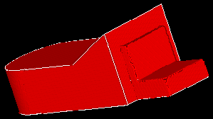 |
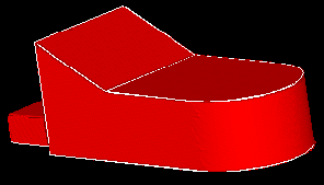
Model invocation is a highly parallel technique designed to select a small number of promising candidates from a large database of objects before full, computationally expensive geometric matching take place.
Matching could be performed with good accuracy with moderately
complex surfaces. Several matching techniques based on interpretation
trees and tree-pruning constraints were analysed and compared
quantitatively. Interval-based geometric reasoning was later
replaced by statistical reasoning on the basis of superior
experimental performance. Object location was solved using methods
based on extended Kalman filters.
 |
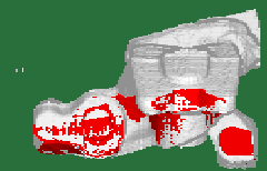 |
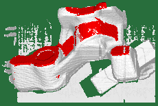
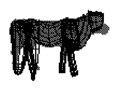
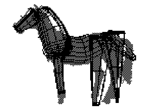
Later research investigated recognizing 3D objects using
range data and parameterized volumetric (geon+superquadric) models.
We see here a cow and horse recognized with the model position,
shape parameters and joint angles estimated. Also of note was the
recognition program could discriminate between various quadrapeds
(and humans) as well as note their similarity.
 |
 |
The Suggestive Modelling System (SMS) developed by MVU is a solid modelling package tailored to the needs of feature-based machine vision. Objects are represented using the features which are likely to be detected by a vision system. SMS allows descriptions by lines, surfaces and volumes, hierarchies of assemblies, viewer-centered representations and sensor-dependent visibility modeling. SMS represents the salient visually identifiable features of objects in a form suitable for a recognition system that primarily receives 3D image evidence (ie, from a 2.5D sketch). SMS represents both structural and viewpoint dependent features and relationships.
Three types of volumetric primitives allow for representation 1, 2, or 3 dimensions of elongated features. These three classes allow alternative recognition pathways to be used based on alternative evidence types. First-order primitives capture the `feel' of the objects: that is, their suggestive and visually salient aspects rather than their metrically accurate character. Second-order primitives allow extra detail to be added, increasing the sensitivity of the method.
Here are some sample models. Click on the images to get a larger picture.
 |
 |
 |
 |
 |
 |
Pose estimation has to cope with two issues: statistical noise and
incomplete information. The IMAGINE project represented uncertainty
using intervals. These were discovered to be too insensitive to integrating statistical
uncertainty although they worked well with lack of knowledge. Therefore the
project investigated using covariance representations instead. Large
covariances represented lack of knowledge and small covariances
represented statistical error. Multiple evidence was fused using a
Kalman filter to reduce uncertainty and eliminate unknown degrees of
freedom.
|
|
|
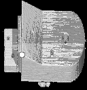
| With one constraint, the model is 90 degrees rotated | With two constraints, the model is slightly to the right of the object. | With three constraints, the model overlies the data almost perfectly. |
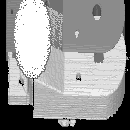
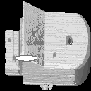
Figure 4. The uncertainty in corner position (marked by the white ellipse) decreases considerably with the addition of extra constraints. The light grey shows the data points, the darker grey is the position of the object as generated by the algorithm.
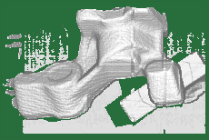
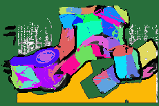
Research since 1987 has been continuing into range data segmentation (for raw 3D points into surface patches). We have developed the rangeseg program that produces some of the best segmentations anywhere of planar and quadratic surfaces from a single range image and the first segmentation program that acts on unstructured 3D point clouds.
 [Raw] [Raw]
|
 [Seg] [Seg]
|
Our research into range scanner hardware produced three results of note:
a) 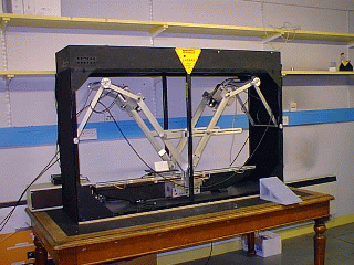
| b) 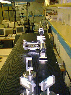
| c) 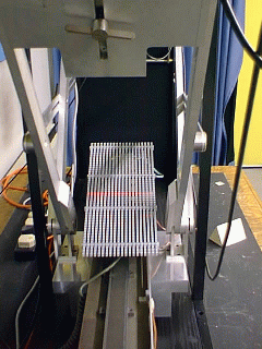
|
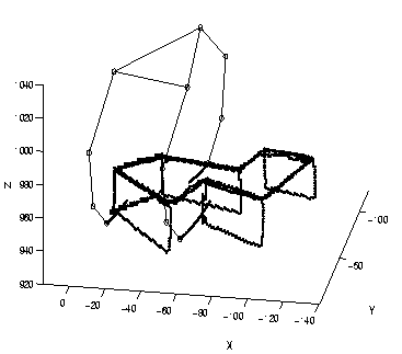
This project investigated using range data to identify points where a robot could grasp an irregularly shaped object. This is useful for applications where little information about the part to be grasped is known in advance, as when retrieving a dropped object from the ocean floor, or collecting radioactive debris. The project built on our experience in locating smooth surface patches to match candidate patches to gripper contacts, evaluate whether a stable grasp is achievable with the proposed contact points, and assess whether the gripper was able to reach the contact points.
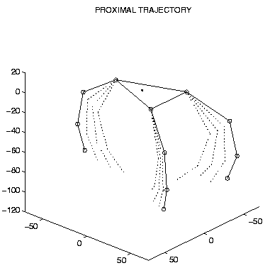
This project was extended from finding grasp points for a robot
parallel gripper to providing the same service for a dextrous robot
hand with many degrees of freedom. The
PhD abstract primarily covering this research is available
on-line.
| a) |
| b) |
|
| c) |
|
The first step in inspecting an industrial part is the acquisition of data corresponding to the part, in our case this means the acquisition of a range image of it. In order to be able to compare the part image and its stored model, it is necessary to align the model with the range image of the part. This process, called registration, corresponds to finding the rigid transformation that superimposes model and image. After the image and model are registered, the actual inspection uses the range image to verify if all the features predicted in the model are present and have the right pose and dimensions. Therefore, besides the acquisition of range images, the inspection of machined parts involves three main issues: modelling, registration and inspection diagnosis.The application for inspection purposes of the main representational schemes for modelling solid objects suggested the use of EDT models.
Our LAIRD industrial object inspection project involved accurately matching spline-based CAD models of geometric and free-form surface objects to range data with position errors of less than 1mm (using range data with an error of 0.15mm). The registered model then guided tolerance-based inspection processes to assess feature shape, size, and position.
More recently Edvaldo Bispo produced a novel approach for the verification of tolerances during the inspection, allowing not only the inspection of the most common tolerances described in the tolerancing standards, but also the inspection of tolerances.
Although 3-dimensional modelling is being used in an increasing number of application areas, the capture of raw, 3-dimensional measurements from real objects has previously required expensive equipment.
In this project we have developed a very inexpensive system for capturing data that requires little more than a PC and a colour video camera. Experiments have shown that the RMS accuracy of measurements taken with the system is around 1mm which, although not as good other much more expensive systems, is sufficient for many consumer-oriented applications.
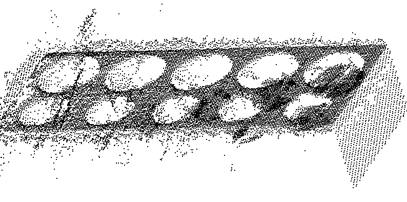
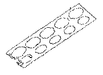
Nearby part features cause inter-reflections and occlusions. Thus, finding manufactured features is much more difficult than the usual surface finding since the data is extremely noisy or sometimes missing altogether. In the picture the main problems can be seen: smudging and flaring of edges, many non-existent `ghost' spots, and very little recoverable depth data. Surfaces containing such artifacts are easy to identify by the existence of patches of `wild' data on an otherwise smoothly modelled surface (or even by visual inspection of the part!).
First we extract out the supporting surface for the artifact and disregard the other surfaces comprising the model. Then we look for discontinuities in that surface that, together with the original surface curvature, give us hints as to what artifacts might be present. This work uses the RANSAC algorithm to find the artifacts, then an evolutionary algorithm to optimise their position and parameters, again using the extra information about them that we have already obtained visually.
|
|
| |||
| a) Raw range data | b) Cosine shaded range data | c) Discontinuities | |||

|
 | ||||
| d) Derived primitives | e) After applying geometric constraints |
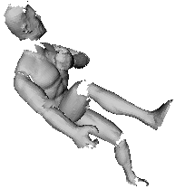 |
The technology now exists for capturing the 3-dimensional shape of real objects and generating 3-dimensional models from this data. These models might be used to visualise the object on a computer display or used in a simulation for science or engineering purposes. Fusing multiple views generally assumes that the part does not change its shape between views, so that feature registration is simplified, and the assumption of rigid geometry provides a common reference frame into which all features can be placed. In this project we have extended the approach to enable models of articulated objects to be reconstructed. An articulated object is an object comprising a number of rigid parts, some of which are connected by joints, such as robot arms or teleoperation manipulators. These models not only describe the shape of the object but also describe the type and location of the joints that connect the multiple parts of the object together. The main initial application of this research is the generation of models suitable for the realistic video imagery, which are then usable for simulation and presentation of teleoperation (e.g. through modelling of robot or teleoperated manipulators) and virtual reality (whether for entertainment, architectural analysis, human-factors analysis) applications. |
This is the first time that articulated models of real, complex objects have been generated automatically from raw, captured, 3-dimensional data.
Some more detailed web pages are also available:
Previous project funding has consisted of:
Other previous projects are described here.