MACHINE
VISION
UNIT
current research
|
MACHINE
VISION current research |
|
Data collection Preprocessing Segmentation and surface fitting Model construction |
Current research topics in the Machine Vision Unit include:
The references under these various headings can also be found all together alongside others on our publications page.
When a realistic 3D computer graphics model is constructed from real scenes, multiple colour texture maps are often necessary. Taking images from different viewpoints and with different camera settings create mismatching colours due to lighting and camera conditions. This colour variation leads to a poor appearance with odd colour tiling on the model surfaces. In order to remove the colour discrepancies, we estimate a set of colour transformations that minimize the total colour error over all overlapping pixels in the images.
Modern manufacturers use a computer CAD model of a part to generate instructions as to how the part can be made. We would like to do the reverse: generate a CAD model from a physical object. This is useful when spare parts are needed for old machinery, when an aesthetic model has been produced by a sculptor, when an existing part has been modified by hand, or when it is necessary to generate `custom fits' to human surfaces such as for protheses.
Data collected from 3D range finders contain no information about the underneath of the object, the part in the shadow of the laser. Therefore these images are known technically as `2.5D', and several such images have to be collected for each object in order for all surfaces to be seen. These images have to be registered and merged in order to collect complete information about the object. Surface shape and orientation is deduced and collected together into a incoherent `model' which normally contains gaps and inconsistencies, errors unacceptable to manufacturers.
Our current work centres on generating a more accurate and coherent model suitable for industrial use.
All solid objects have geometric constraints which can be exploited by the modelling process. For example, surfaces meet other surfaces, and do not cut through each other.
The models needed by industry are generally designed with more rigid feature relationships. The consideration of these relationships is actually necessary because some attributes of the object would have no sense if the object modelling scheme did not take into account these constraints. For example, take the case when we want to estimate the distance between two parallel planes: if the plane fitting results gave two planes that are not parallel, then the distance measured between them would have no significance.
Exploiting these relationships is useful for reducing the effects of registration errors and mis-calibration, thus improving the accuracy of the estimated part features' parameters and consequently the quality of the modelling.
We are using classical and evoluationaryoptimisation techniques to incorporate this extra knowledge into the modelling process.
For several years our research group at Edinburgh University has been exploring 'knowledge based' techniques to overcome the problem of 'frozen in' errors from both data and parametric surface driven approaches to data. The idea being to exploit known general knowledge about the domains of the objects being reconstructed. This is possible as most normal objects and buildings follow standard conventions arising from tradition, utility or engineering design. An assumption of this work is that the reverse engineering process need not be fully automated.
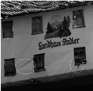
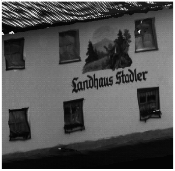
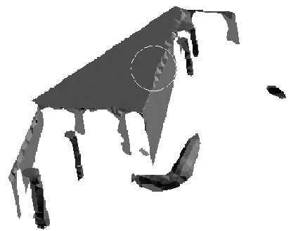
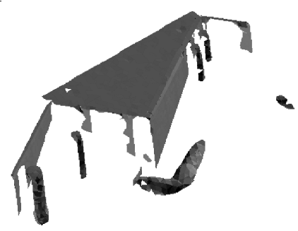
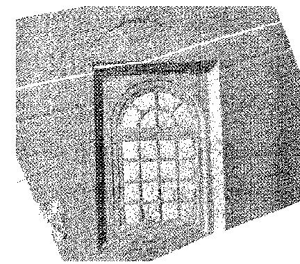
Using a constrained distance algebraic distance approach that applies specific constraints on all of the individual surfaces constrained recovery of 3D shapes is possible. Within this framework we simultaneously apply constraints that encode standard feature relationships such as alignment of surfaces, colinearity of features, etc. This reverse engineering technique has been applied to both industrial parts and architectural scenes. Looking at the example below it can be seen that ripples near the windows obtained from the original triangulation (on the left) have been flattened.
 |
 |
Particularly difficult problems for data-driven recovery approaches are outliners, low resolution and noisy data on reflective surfaces. When we have knowledge of either the specific parts or of general design relationships that hold in a particular domain, then we can exploit this knowledge in the shape recovery process.
The figure below shows an example of a surface fitting problem with a cylindrical surface that has a tangent joint to another cylindrical surface. Data driven approaches have trouble identifying a clean boundary as surface shape variations are not distinguishable within the data noise. Using knowledege of the type of junction allows an estimate of the interface and its parameters such as cylindrical axes, radii and intersections for this example.
 |
 |
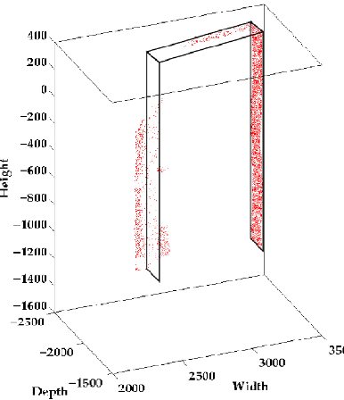
Using the parametric model with a constrained optimization method applied to architectural feature recovery estimates the position and shape that best fits the data fragments as well as segmenting the data via assigning appropriate 3D points to the fitted model surfaces. The figure shows an example doorway fit.
 |
 |
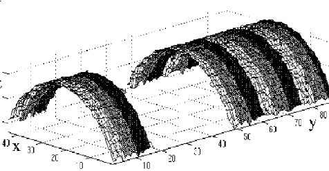
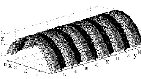
To reduce aquisition costs it is desirable to reduce the number of scans required by minimizing the number of scans while still maintaining complete coverage. For this reason researchers have developed view planning algorithms. Full recovery via this approach can be infeasible from a practical point of vire so we have recently been investigating knowledge-based hypothetical reconstruction of unobeserved surfaces. The key is the knowledge that the shape of an unobserved surface is usually the same as that of the observed surface. Applying the recovery process to planar and cylindrical surfaces can be seen in figure 4. As well as the recovery of surface shape, the recovery of surface appearance, is also possible. Here the consistency of appearance is exploited, specifically either constant reflectance or repeated surface texture.
 |
 |
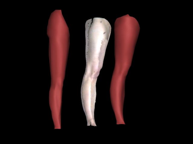
We also investigated techniques for constructing fully articulated and accurately deformable models of human from scanned data (with resources provided by the Edinburgh Virtual Environment Centre (EdVEC)). This also utilizes domain knowledge to infer the presence of an interior skeletal hierarchy around which a parametric model of the body is formed and driven. Again, the aim is to minimise the cost (in both time and data) by selectively capturing regions of the body in a variety of unique poses representative of the human range of movement. This data then form the basis of a number of training sets, which must be further simplified and aligned to capture the properties of musculature - as illustrated below in the figure of a sample leg dataset being conformed to a generic mesh.
 |
Finally we have been researching the use of evolutionary methods for surface fitting and 3D shape recovery. These bring the advantages of Euclidean, robust error metrics and are easily incorporated into the evaluation criteria and initialising the optimization is not a big problem with the use of multiple 'chromosomes' as the starting points. The main disadvantage is the extra computational cost that arises in the parameter search space instead of parametric surface growing in data space. As reverse engineering is a one time process this is not seen as a problem.
Link to ReferencesThe CAMERA (CAd Modelling of built Environments from Range Analysis) project is a multi-site, EU initiative investigating the automated acquisition of architectural CAD models of already built environments such as industrial or heritage buildings. The goal is to take range and intensity images of a site and construct a "virtual reality" model of the building. Such models can be placed on the internet, allowing remote access. Among the applications are remote scene inspection, maintenance, 3D tourist models, 3D building catalogue, architecture, archaeology, etc.
Range sensors used in environment recovery have a wide (panoramic in some cases) field of view, and the task of completely recovering an environment is performed usually by placing the sensor on a tripod, taking some views by moving the sensor manually, and merging the views together to build the model.
Although general interest environments, like heritage buildings, are not always suitable for a mobile robot to navigate inside, in some cases it is feasible to fully automate the process of scan acquisition by using a sensor mounted on such a robot. The robot is instructed to do the work in a more intelligent way by taking into account some considerations to find the next best position to place the sensor. Such cases could include, for example, wide corridors or empty rooms with interesting features such as in a monastery, palace or castle; or a large interesting object to be fully mapped around.
This work is focussed on developing a methods for obtaining a complete and accurate three-dimensional recovery of an unknown indoor environment, placing the sensor at the best position each time. Different views are used to build up an incremental environment model. So one problem is stated as finding the next view that would best improve the current recovered model.
Another line of research associated with this work is viewpoint estimation, where the position of the 3D imager is calculated from a data set so that the 3D image can be enhanced.
Link to ReferencesTraditional image analysis processes the image into symbolic scene descriptions before any model matching is considered. In iconic vision we investigate the possibilities of using the image itself more directly. Some processing is done to reduce the bulk of the data, but this is constrained in our system to follow biologically plausible rules. Previous research investigated iconic model matching. The visual attention mechanism is the focus of our current research.
We investigate the question of whether or not it is possible to learn visual objects and their geometric relationships in the context of an attention changing vision system that uses image-based representations rather than 3D representations.
An initial question in our project was: can we learn primal sketch features in a log-polar image representation using a neural network and, if so, how good is that when compared to previous approaches? The answer was yes, and the results were better.
The current question of interest is: is it possible to incrementally represent object features and understand how they relate to each other by looking at a sequence of primal sketch based images?
More details of our project including an explanation of log-polar plots and primal sketches are available on another page.
This project began in Octorber 2002 with the main objective being to address the scientific question: 'Can rich descriptions from foveal and other image sensors, selected by a hierarchial visual attention process, being guided and processed using task, scene, function, and object contextual knowledge improve image-based recognition processes?' The two applications the project addresses are:
To address the main scientific question, the project is researching methods for:
The results will be integrated in a complete closed-loop object and situation recognition system. The CAVIAR website can be found here.
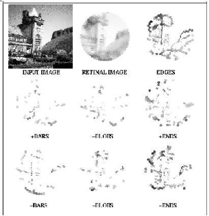
Traditional image extraction operators have usually been designed by hand and act on Cartesian images. The organisation of the pimate visual system appears to be different. The mapping from retina to the visual cortex can be mathematically approximated using a log-polar representation. We have shown that primal sketch features can be extracted using symmetry operators and a PCA pre-processing module which precede a set of neural networks to learn a feature's class and contrast. Figure 8 illustrates the results of the system after training with synthetic features and a few manually extracted real features.
 |
Machine vision has recently shown increasing interest in modelling visual attention and a number of computable models of attention have been developed. These traditional models of attention in computer vision focus on the space-based Saliance models and do not account for recent research findings on object-based attention. Space-based models may fail to work in real environments that are cluttered or where objects overlap. This is because attention may need to work in discontinuous spatial regions/locations at the same time, attention may need to select and object composed of different features but from the same region of space and normal objects are hierarchically structured.
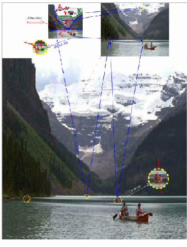
We are investigating a mechanism that has object based visual attention integrated with space based visual attention and has a hierarchical selectivity mechanism for visual attention. Figure 7 below shows the overall attention movements implemented for an outdoor scene from an example saccade order up/down scales. Red and blue arrows indicate that attention shifts between resolutions. Arrows with red solid circles denote attention is attending the top groupings. As can be seen from the figure there are substantial shifts of visual attention for this natural scene.
 |
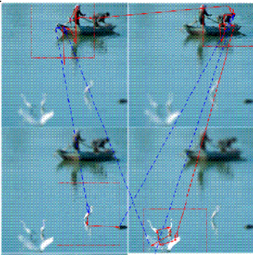
A model of selective attention has been proposed based on space-varient data structures. Selective mechanisms for reducing the high computational burden of selective attribution have been proposed on space variant data structures or multi-resolution pyramid representations. As well as the overt attention systems to guide fixations of saccadic eye movements and we have investigated and developed covert attention mechanisms. The low-level features are extracted from the currently foveated region and top-down priming information are derived from previous matching results to compute the salience of the candidate foveate points. A suppression mechanism is then employed to prevent constantly re-foveating the same region. Figure 8 shows the effect of combining saccading with foveation.
 |